Altium Schematic Symbol Multiple Parts
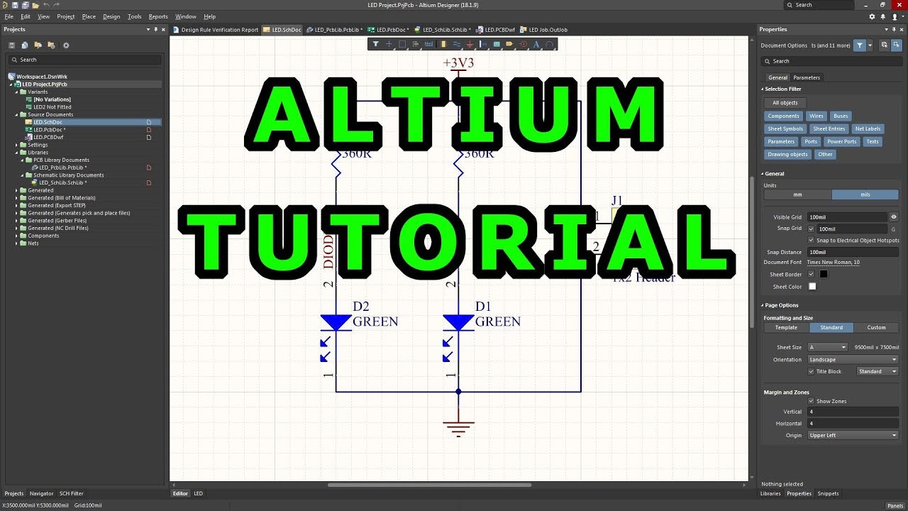
Altium error: nets containing multiple input ports. what does this Tutorial 1 for altium beginners: how to draw schematic and create Altium schematic component
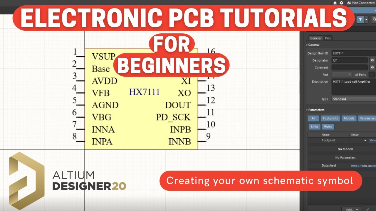
Altium Designer 20 Tutorials - How to create a schematic symbol - YouTube
Altium schematic component Schematic symbol generation tool Altium designer 20 tutorials
Component schematic create symbol draw altium pcb 3d
Tutorial 1 for altium beginners: how to draw schematic and createAltium schematic numbers quickly wizard Altium designer: modify ic symbols in-sheet to increase spaceAltium tutorial-14: how to design multi-part symbols in altium/design.
Creating pcb multiple part components and symbols in altium designerAltium components schematic pcb Altium sheet symbols designer modify ic increase space electrical componentAltium symbols.
Creating pcb multiple parts components and symbols in altium designer
Schematic create component symbol draw altium pcb 3d property setSchematic symbol altium tool generation designer documentation wizard interface dialog access How to create schematic symbols in altium designerAltium schematic symbols draw tutorial create.
Altium multiple nets input ports error containing mean does electrical stack imgur .

Schematic Symbol Generation Tool | Altium Designer 15.1 User Manual

How to Create Schematic Symbols in Altium Designer | Blog | Altium

Altium Schematic component - Create a new component, draw schematic

Creating PCB Multiple Parts Components and Symbols in Altium Designer

Creating PCB Multiple Part Components and Symbols in Altium Designer

Altium Designer: Modify IC symbols in-sheet to increase space

Altium error: Nets containing multiple input ports. What does this

Altium Schematic component - Create a new component, draw schematic
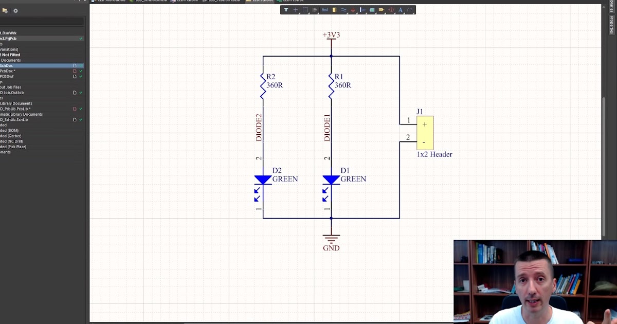
Tutorial 1 for Altium Beginners: How to draw schematic and create
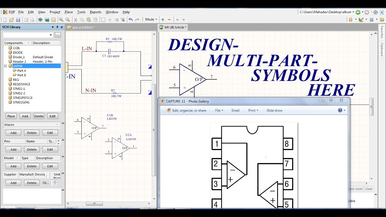
ALTIUM TUTORIAL-14: How To Design MULTI-PART SYMBOLS IN ALTIUM/Design